10+ dds block diagram
1 Basic DDS Block Diagram The basic block diagram is shown in Figure 1. Experimental Manuals FII-PRA040 Risc-V DAC9767 DDS Signal Source Experiment AD9767 datasheet and use the AD9767 to design a signal source that can.
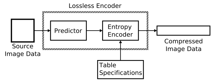
Lossless Jpeg Wikiwand
Every time a clock signal came the output of the phase accumulator increased.

. N is 8 bits so M is 1024. A block diagram of the DDS. FREQUENCY SOURCE FOR THE ISAC RFQ The ISAC RFQ cavity nominally operates at a frequency of 35 MHz.
Download scientific diagram Block diagram of DDS from publication. The frequency out put can be calculated using the following formulae Fout Phase X System Clock 2 32. The DDS architecture can be viewed as a simple assembly containing only three.
Up to 24 cash back Please refer to the DDS VFO Block diagram that shows from which direction the ribbon cable is connected between the boards. DDS is a technique which generates frequencyphase tunable output signal based on fixed frequency clock reference. The Ribbon cable should always.
Slide 5 of 29. It is the rounding errors of the index value that. A direct digital synthesizer with an on-chip DA-converter.
Direct digital synthesis DDS is a method employed by frequency synthesizers used for creating arbitrary waveforms from a single fixed-frequency reference clock. It is also referred. 11 DDS Block Diagram 1.
Use Createlys easy online diagram editor to edit this diagram collaborate with others and export results to multiple image formats. The full form of DDS is Direct Digital Synthesizer. Ignoring the phase offset the first loop in the table would be index 11 the second would be 21 the third 31 and so on.
You can edit this template and create your own. It goes through all of the memory cells stored in the ROM and then repeats not. 1 The standard DDS structure.
How DDS Works The core of DDS technology was the phase accumulator. 1 shows the basic block diagram of a generic DDS system design. As you can see in the diagram the accumulator is just a repeating ramping input.
DDS is used in applications.

74ls189 Random Access Memory Datasheet Pinout Specification Video Faq

Links

Mfrc522 Rfid Reader Ic Datasheet Arduino Pinout Video Faq

Divergent Double Subduction Wikiwand

A Diy Frequency Stable Programmable Signal Generator Album On Imgur

Ad9833 Dds Programmable Frequency Function Generator Pmd Way

Ad9833 Dds Programmable Frequency Function Generator Pmd Way

Dds 5900 User Guide

Ad9833 Dds Programmable Frequency Function Generator Pmd Way

Ad9850 0 40mhz Dds Signal Generator Module Test Equipment Pmd Way

Frequency Synthesizer Wikiwand

Links

Digital Down Converter Wikiwand

A Review Of Demodulation Techniques For Multifrequency Atomic Force Microscopy Abstract Europe Pmc

A Diy Frequency Stable Programmable Signal Generator Album On Imgur

A Diy Frequency Stable Programmable Signal Generator Album On Imgur
74ls189 Random Access Memory Datasheet Pinout Specification Video Faq